Introduction
This document introduces the topic of voice dial peers and call legs. It explains the call setup process through a packet network that uses Cisco IOS® software voice-enabled gateways/routers.
For other topics that discuss dial peers, see the Related Information section of this document.
Prerequisites
Requirements
There are no specific requirements for this document.
Components Used
This document is not restricted to specific software and hardware versions.
Types of Dial-Peers
Cisco IOS uses two types of dial-peers. They are defined as:
- Plain old telephone systems (POTS) dial peer – These define the characteristics of a traditional Telephony network connection. The POTS dial peer maps a dial string to a specific voice port on the local router/gateway. Normally, the voice port connects the router/gateway to the local public switched telephone network (PSTN), private automatic branch exchange (PBX), or telephone.
- Voice-Network dial peers – These define the attributes of a packet voice network connection. Voice-Network dial peers map a dial string to a remote network device. Some examples of these remote network devices are listed here:
- Destination router/gateway
- Cisco CallManager
- Session initiation protocol (SIP) server (for Voice over IP SIP)
- Open Settlement Protocol (OSP) server (for Voice over IP that uses settlement)
- H.323 Gatekeeper
- Mail Transfer Agent (MTA) Server (for Multimedia Mail over IP scenarios)The specific type of Voice-Network dial peer depends on the packet network technology used. Different technologies used by dial peers are explained here:
- Voice over IP (VoIP) – The dial peer is mapped to the IP address, Domain Name System (DNS) name, or server-type of the destination VoIP device that terminates the call. This applies to all VoIP protocols such as H.323, SIP, and Media Gateway Control Protocol (MGCP).
- Voice over Frame Relay (VoFR) – The dial peer is mapped to the data-link connection identifier (DLCI) of the interface from which the call exits the router.
- Voice over ATM (VoATM) – The dial peer is mapped to the ATM virtual circuit for the interface from which the call exits the router.
- Multimedia Mail over IP (MMoIP) – The dial peer is mapped to the e-mail address of the Simple Mail Transfer Protocol (SMTP) server. This type of dial peer is used for Store and Forward Fax (on-ramp and off-ramp faxing).
The Cisco IOS command to enter into the dial peer configuration mode is:
maui-nas-07(config)#dial-peer voice number ?

  pots   Telephony
  voatm  Voice over ATM
  vofr   Voice over Frame Relay
  voip   Voice over IP
Relationship Between Dial Peers and Call Legs
A voice call over a packet network is segmented into discrete call legs. These are associated with dial-peers (a dial-peer is associated with each call leg). A call leg is a logical connection between two router/gateways or between a router/gateway and an IP Telephony device (for example Cisco CallManager, SIP Server, and so forth). To illustrate this concept, see Figure 1 and Figure 2 here:
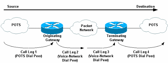
Figure 1. Voice Dial Peers / Call Legs Toll-bypass Scenario

In Figure 1 (toll-bypass), a voice call comprises four call legs, two from the perspective of the originating router/gateway and two from the perspective of the terminating router/gateway.
Figure 2. Voice Dial Peers / Call Legs: Call Manager System with IOS Gateway Scenario
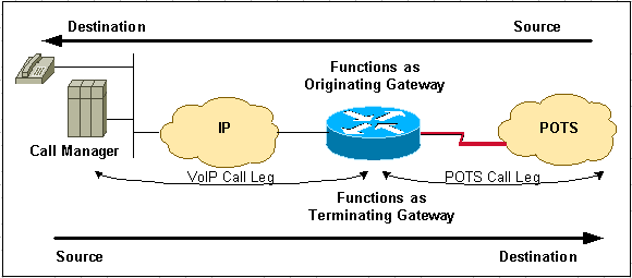
In the Figure 2 (CallManager system with IOS Gateway), a voice call compromises two call legs.
Note: The terms originating router/gateway and terminating router/gateway are dependent on the source to destination direction of the call.
Note: Hair-Pinning is the name given to calls that originate and terminate on the same router/gateway. On POTS-to-POTS Hair-Pinning calls, the router/gateway matches an inbound POTS dial-peer and an outbound POTS dial-peer to terminate the call. This is supported on POTS interfaces. However, VoIP-to-VoIP Hair-Pinning is not supported on Cisco IOS voice-enabled platforms except in CallManager Express with certain IOS releases.
Call Setup Process
A call is segmented into call legs with a dial peer associated to each call leg. The process for this is listed here:
- The POTS call arrives at the originating router/gateway. An inbound POTS dial-peer is matched. (See Note 3 later in this document).
- After it associates the incoming call to an inbound POTS dial-peer, the originating router/gateway creates an inbound POTS call leg and assigns it a Call ID (Call Leg 1 in Figure 1).
- The originating router/gateway uses the dialed string to match an outbound Voice-Network dial-peer.
- After it associates the dialed string to an outbound Voice-Network dial-peer, the originating router/gateway creates an outbound Voice-Network call leg and assigns it a Call ID (Call Leg 2 in Figure 1).
- The Voice-Network call requests arrive at the terminating router/gateway. An inbound Voice-Network dial-peer is matched.
- After the terminating router/gateway associates the incoming call to an inbound Voice-Network dial peer, the terminating router/gateway creates the inbound Voice-Network call leg and assigns it a Call ID. (Call Leg 3 in in Figure 1)
- The terminating router/gateway uses the dialed string to match an outbound POTS dial-peer.
- After it associates the incoming call setup to an outbound POTS dial peer, the terminating gateway/router creates an outbound POTS call leg. It assigns it a Call ID, and terminates the call. (Call Leg 4 in Figure 1)
In scenarios where a Cisco CallManager is present with a Cisco IOS router/gateway assume these :
- For outbound calls from the CallManager system through an IOS router/gateway, the IOS router/gateway behaves as a terminating device.( See steps 5 through 8)
- For inbound calls to the CallManager system through an IOS router/gateway, the IOS router/gateway behaves as an originating device. ( See steps 1 through 4)
Note: At this stage, if configured on the inbound POTS dial-peer, non-default inbound POTS services and/or Toolkit Command Language (TCL) applications are used. When you use such services or applications, it is important to be certain that the correct inbound POTS dial-peer is matched. Some examples of services / applications include:
- DID (direct inward dial)
- TCL Based Applications such as IVR ( interactive voice response), VoIP SIP Transfer, On-Ramp Faxing (in the context of Store and Forward Fax).For more information, refer to Voice – Understanding How Inbound and Outbound Dial Peers are Matched on Cisco IOS Platforms.
Note: At this point, both routers/gateways negotiate Voice-Network capabilities and applications (if required). Default capabilities are not displayed on the router/gateway IOS configuration output. Use the command show dial-peer voice number to view the configured capabilities, services, and applications on POTS and Voice-Network dial-peers.
- Default capabilities include codec g729r8, vad enable, dtmf-relay disable, fax-relay disable, req-qos best-effort, acc-qos best-effort, and session protocol cisco (for H.323).
- Examples of TCL applications include Remote IP Authentication and Off-Ramp Faxing.
Note: When non-default capabilities or applications are requested by the originating router/gateway, the terminating router/gateways needs to match an inbound Voice-Network dial-peer that is configured for such capabilities or applications.
Related Information
- Understanding Inbound and Outbound Dial Peers on Cisco IOS Platforms
- Understanding Inbound and Outbound Dial Peers Matching on IOS Platforms
- Understanding the Operational Status of Dial-Peers on Cisco IOS Platforms
- Understanding Direct-Inward-Dial (DID) on Cisco IOS Digital (T1/E1) Interfaces
- Configuring Dial Plans, Dial Peers, and Digit Manipulation
- Unified Communications Product Support
- Troubleshooting Cisco IP Telephony
- Technical Support & Documentation – Cisco Systems
Source: Understanding Dial Peers and Call Legs on Cisco IOS Platforms