Cisco Borderless Network Architecture
The Unified Access Solution uses at its foundation the Cisco Borderless Network architecture and the Cisco Borderless Campus Design principles. All Unified Access elements work on top of this architecture, which is specifically designed to provide the proper foundational features needed for the Unified Access services being deployed. This chapter describes the foundational principles of the Cisco Borderless Network Architecture and provides specific guidance to design an intelligent network infrastructure to handle borderless services. We discuss the design choices, switching platforms, and network features you need to understand about the intelligent network that Unified Access solutions use to solve business problems.
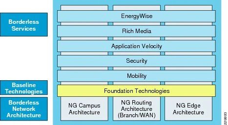
The Cisco Borderless Network architecture is a next-generation architecture that allows different elements of the network, from access switches to wireless access points, to work together and allow users to access resources from anywhere at anytime. The Cisco Borderless Network integrates key services into the network fabric while increasing reliability and security and decreasing outages. For such an infrastructure, the enterprise network must be developed with an architectural approach that embeds intelligence, simplifies operations, and scales to meet future demands. The Cisco Borderless Network is composed of several modular components, as illustrated in Figure 2-1.
Figure 2-1 Cisco Borderless Network Framework

Each building block in the Cisco Borderless Network framework is designed to offer the following components:
•Network Infrastructure—Builds enterprise campus, WAN, and edge networks as an open platform that can provide secure and intelligent services at the access layer, aggregation scalability, and a high-performance backbone solution to enable end-to-end borderless services and applications.
•Foundation Technologies—Common baseline technologies that are integrated across various enterprise architectures to optimize service delivery, intelligently differentiate between various applications, and build a highly-available network infrastructure.
•Borderless Services—Enables the end-to-end borderless user experience to provide ubiquitous connectivity to enterprise users and devices with security, reliability, and sustainability. It empowers network architects to leverage the network as a platform to offer rich services to reduce business operational costs, increase efficiency through green practices, and much more.
Borderless Campus Network Design
The Borderless Campus Network architecture is a multi-campus design, where a campus consists of multiple physical buildings with a wide range of network services that offer the capability for anyone to securely access network resources from anywhere at anytime, as shown in Figure 2-2.
Figure 2-2 Borderless Campus Network Design

The Cisco Borderless network architecture focuses on the campus framework and network foundation technologies that provide a baseline of routing, switching, and several key network services. The campus design connects infrastructure components, such as devices in the access layer, the services block, the WAN, and so on, to provide a foundation on which mobility, security, and management, as well as other key services, can be integrated into the overall design.
The Cisco Borderless Campus provides guidance on building next-generation enterprise networks, which with the addition of critical network technologies become the framework to deliver the foundation for Unified Access. This chapter details the approach of the Cisco Borderless Network Architecture and is divided into these sections:
•Campus design principles—Provides proven network design choices to build various types of campus infrastructure.
•Campus design model for the enterprise—Leverages the design principles of a tiered network design to facilitate a geographically-dispersed enterprise campus network made up of various elements.
•Considerations of a multi-tier campus design model for enterprises—Provides guidance for the enterprise campus LAN network as a platform with a wide range of next-generation products and technologies to seamlessly integrate applications and solutions.
Borderless Campus Network Design Principles
The Borderless Campus requires maximum availability, flexibility, security, and manageability. The use of sound network design principles ensures that the network will deliver on current requirements as well as be prepared for future services and technologies. Design guidelines that are built upon the following principles allow the enterprise network architect to build a geographically-dispersed borderless network:
•Hierarchical
–Facilitates understanding the role of each device at every tier
–Simplifies deployment, operation, and management
–Reduces fault domains at every tier
•Modularity—Allows seemless network expansion and integrated service enablement on-demand
•Resiliency—Satisfies user expectations for keeping the network available
•Flexibility—Allows intelligent traffic load sharing by using all network resources
These are not independent principles. The successful design and implementation of a campus network requires an understanding of how each of these principles applies to the overall design. In addition, understanding how each principle fits in the context of the others is critical in delivering the hierarchical, modular, resilient, and flexible network required by enterprises.
Designing the Borderless Campus network in a hierarchical fashion creates a flexible and resilient network foundation that allows network architects to overlay the security, mobility, and management features essential to the Unified Access Solution. The two proven, time-tested hierarchical design models for campus networks are the three-tier layer and the two-tier layer models, as shown in Figure 2-3.
Figure 2-3 Three-Tier and Two-Tier Campus Design Models
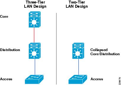
The key layers are access, distribution, and core. Each layer can be seen as a well-defined structured module with specific roles and functions in the campus network. Introducing modularity into the campus hierarchical design further ensures that the campus network remains resilient and flexible to provide critical network services as well as to allow for growth and changes that may occur over time.
•Access layer
The access layer represents the network edge, where traffic enters or exits the campus network. Traditionally, the primary function of an access layer switch is to provide network access to the user. Access layer switches connect to distribution layer switches to perform network foundation functions such as routing, quality of service (QoS), and security.
To meet network application and end user demands, next-generation Cisco Catalyst switching platforms no longer simply switch packets, but now provide more integrated and intelligent services to various types of endpoints at the access layer. Building intelligence into access layer switches allows them to operate more efficiently, optimally, and securely.
•Distribution layer
The distribution layer interfaces between the access layer and the core layer to provide many key functions, including:
–Aggregating access layer wiring closet swithces
–Aggregating Layer 2 broadcast domains and Layer 3 routing boundaries
–Providing intelligent switching, routing, and network access policy functions to access the rest of the network
–Providing high availability through redundant distribution layer switches to the end user and equal cost paths to the core, as well as providing differentiated services to various classes of service applications at the access layer
•Core layer
The core layer is the network backbone that hierarchically connects several layers of the campus design, providing for connectivity between end devices, computing, and data storage services located within the service block and other areas within the network. The core layer serves as the aggregator for all the other campus blocks and ties the campus together with the rest of the network.

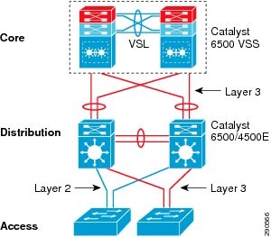
Figure 2-4 shows a sample three-tier campus network design for enterprises where the access, distribution, and core are all separate layers. To build a simplified, scalable, cost-effective, and efficient physical cable layout design, Cisco recommends building an extended-star physical network topology from a centralized building to all other buildings on the same campus.
Figure 2-4 Three-Tier Campus Network Design Example
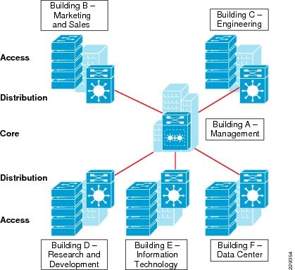
The primary purpose of the core layer is to provide fault isolation and high-speed backbone connectivity with several key foundational services. Isolating the distribution and core into separate layers creates a clean delineation for change control activities affecting end devices and those that affect the services block, WAN, or other parts of the campus network. A core layer also provides for flexibility in adapting the campus design to meet physical cabling and geographical challenges. If necessary, a separate core layer can use a different transport technology, routing protocols, or switching hardware than the rest of the campus, providing for more flexible design options when needed.
In some cases, because of either physical or network scalability, having separate distribution and core layers is not required. In smaller campus locations where there are fewer users accessing the network or in campus sites consisting of a single building, separate core and distribution layers may not be needed. In this scenario, Cisco recommends the alternative two-tier campus network design, also known as the collapsed core network design.
Figure 2-5 shows an example of a two-tier campus network design for small enterprise campus locations where the distribution and core layers are collapsed into a single layer.
Figure 2-5 Two-Tier Network Design Example
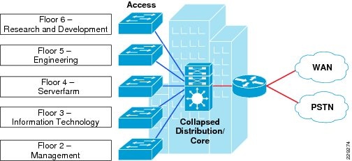
If using the small-scale collapsed campus core design, the enterprise network architect should understand the network and application demands so that this design ensures a hierarchical, modular, resilient, and flexible campus network.
Borderless Campus Network Design Models
Both campus design models (three-tier and two-tier) have been developed with the following considerations:
•Scalability—Allowing for network speeds from 100mb to 10gb, the ability to scale a network based on required bandwidth is paramount. The network provides investment protection by allowing for upgradability as bandwidth demand increases.
•Simplicity—Reducing operational and troubleshooting cost by the use of network-wide configuration, operation, and management.
•Resiliency—Ability to provide non-stop business communication with rapid sub-second network recovery during network failures or network upgrades.
•Cost-effectiveness—Integrated network components that fit budgets without compromising design principles and network performance.
As shown in Figure 2-6, multiple campuses can co-exist within a single enterprise system that offers borderless network services.
Figure 2-6 Borderless Campus Network Design Model
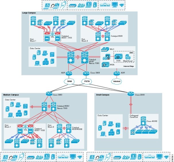
Depending on the size and number of users and devices on the medium and small campuses, their relative network size should be less than the large campus. Hence compared to the large campus network, the medium and small campus sites may have alternative network designs that can provide network services based on overall campus network capacity.
Using high-speed WAN technology, several medium and small enterprise campuses can interconnect to a centralized large campus that provides secure shared data and network services to all the employees independent of their physical location.
Table 2-1 shows a summary of the Borderless Campus Network design models as they are applied in the different enterprise network designs.
| Enterprise Location | Recommended Campus Design Model |
| Large campus | Three-tier |
| Medium campus | Three-tier |
| Small campus | Two-tier |
Large Campus Network Design
The large campus in the Borderless Campus consists of a centralized hub that interconnects several medium and small campuses to provide end-to-end access to resources and borderless services. The network in the large campus is larger than the medium and small campuses and includes end users, devices, servers, security, mobility, and management devices. Multiple buildings of various sizes exist in one location, as shown in Figure 2-7.
Figure 2-7 Large Campus Reference Design

The large campus utilizes a three-tier campus design model to meet all key technical requirements and provide a strong, well-structured network foundation. The modularity and flexibility of the three-tier campus design allows for easier expansion of the large campus network and keeps all network elements protected and available.
To enforce external network access policy, the large campus also provides external gateway services to employees to access the network to and from the Internet.
Medium Campus Network Design
From a network size perspective, the medium campus is not much smaller than the large campus. Geographically, it can be distant from the large campus and require a high-speed WAN circuit to interconnect the campuses. The medium campus can also be considered as an alternative campus to the large campus, with the same common types of applications, endpoints, users, and network services. Similar to the large campus, separate WAN devices are recommended to provide access to the large campus, given the size and number of employees at this location.
Similar to the large campus network design, Cisco recommends the three-tier campus design model for the medium campus, as shown in Figure 2-8.
Figure 2-8 Medium Campus Reference Design
Small Campus Network Design
The small campus is typically confined to a single building that spans across multiple floors with different organizations. The network scale in this design is smaller compared to the large and medium campuses, however application and borderless services demands are the same as in the medium and large campuses.
In a smaller campus network deployment, the distribution and core layer functions can be collapsed into the two-tier design without compromising basic network requirements. Prior to deploying the collapsed core and distribution system, network architects must consider scale, expansion, and manageability of the network to ensure the network meets current and future enterprise requirements.
The necessary WAN bandwidth must be assessed appropriately for the small campus network design. Although the network size is reduced compared to other campuses, sufficient WAN capacity is needed to deliver an appropriate collapsed core and distribution design. This alternative and cost-effective network design is recommended only in smaller locations and only when WAN traffic and application needs must are considered before choosing this model. Figure 2-9 shows the small campus network design in more detail.
Figure 2-9 Small Campus Reference Design

Multi-Tier Borderless Campus Design Models
This section provides more detailed network infrastructure guidance for each tier in the campus design model. Each design recommendation is optimized to keep the network simplified and cost-effective without compromising network scalability, security, and resiliency.
Campus Core Layer Network Design
The core layer is the center-point of the network and a high-speed transit point between multiple distribution blocks and other systems that interconnect to the services block, the WAN, and the campus edge. The common design in large networks is to build a high-performance, scalable, reliable, and simplified core.
When network architects are designing a campus core, it becomes imperative take into consideration network scalability, capacity, and reliability to allow for high-performance end-to-end borderless services. Determining the core layer scalability and performance may be challenging as it varies depending on the needs of the enterprise. In campus core design, large enterprise networks are largely built with highly-resilient systems and high-speed 10Gbps links. Network architects must proactively foresee the expansion, evolution, and advancement of devices and applications on the network that may impact the core.
Cisco recommends building the next-generation borderless campus core with following principles:
•The architecture should be designed to support modern technologies that enable advanced networking and integrated services to solve key business problems.
•Scalability to adapt to enterprise network needs, as well as the ability to provide for intelligent borderless network services.
•Flexible design options that maximizes return on investment (ROI) and reduces total cost of ownership (TCO).
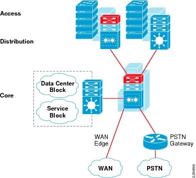
These design principles are important when designing the core network so that the core is capable of addressing current and future borderless network demands. Cisco recommends the Cisco Catalyst 6500-E and Nexus 7000 switching platforms for the core of the next generation borderless campus. These multi-terabit switching platforms are designed with a robust hardware architecture that exceeds the foundational borderless campus requirements. Figure 2-10 illustrates core designs for building the next-generation Borderless Campus Core.
Figure 2-10 Core Layer Design Model Options

Cisco Catalyst 6500-E
The industry-leading and widely-deployed Cisco Catalyst 6500-E series platform is the lead system to deploy in a borderless campus core role. Because of its advanced hardware and software innovations, the Catalyst 6500-E switching platform is the preferred way to build an enterprise-class borderless campus core network. The Cisco Catalyst 6500-E switches have a flexible architecture that enables a rich set of features and advanced technologies, along with the high-speed interfaces needed for the borderless campus. In large and medium campuses, bandwidth intensive and latency sensitive applications—such as real-time IP-based voice and video—are ubiquitous, so network architects must take this into consideration when selecting the appropriate core platform. As networks expand, the management and troubleshooting of the infrastructure increases, however administrators can leverage Cisco’s virtualization technology (VSS) to ease those burdens.
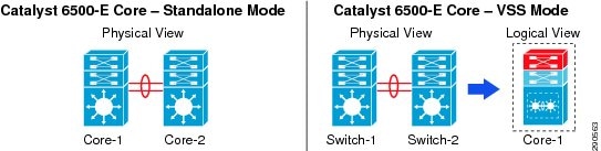
To provide mission-critical network services, it is recommended that the core layer be deployed with high resiliency, such as using dual Cisco Catalyst 6500-E systems. Deploying resilient standalone core layer switches with redundant hardware provides constant network availability for business operation during faults and also provides the ability to load share high-speed network traffic between different blocks (e.g., distribution and service block). A redundant core network design can be deployed in a traditional standalone model or in a Virtual Switching System (VSS) model. The campus core layer network design and operation broadly differ when the core layer is deployed as a standalone, which operates all three planes (forwarding, control and data planes) in isolation. However with Cisco VSS technology, two core systems are clustered into a single logical system and the control and management planes get combined on the systems to produce a single logical Catalyst 6500-E core system.
The standalone/VSS physical and operational view is shown in Figure 2-11.
Figure 2-11 Standalone/VSS Physical and Operational View
Cisco Nexus 7000
In high-speed and dense networking environments, enterprises require a simplified network architecture that expands the infrastructure’s scalability, performance, and reliability. With this in mind, Cisco developed the Nexus 7000 switching platform, a powerful multi-terabit switching platform which delivers these fundamental requirements. Cisco’s next-generation data center architectures are built using the Cisco Nexus product family and the Cisco Nexus 7000 platform leads in data center core and aggregation networking.
Because of its unique architecture, technical advantages, and ability to deliver a baseline of campus core requirements, the Cisco Nexus 7000 series can be an alternative platform for deployment in the campus core. In campus core environment, the Cisco Nexus 7000 offers un-paralleled 10G density to aggregate distribution blocks. It enables low-latency and wire-speed backbone connectivity between the service block and campus edge. The Nexus 7000 uses the Cisco NX-OS operating system, which is a highly evolved, multithreaded, and modular operating system to deliver core-class networking services and flexibility. NX-OS offers resilient network communication, system virtualization, and several other technical innovations that enable the capabilities needed for the next-generation Borderless Campus network. The Nexus 7000 platform operates in a standalone configuration that locally maintains the control, distributed forwarding, and management planes. For a resilient and mission-critical campus core design, the Cisco Nexus 7000 system should be deployed with resilient hardware components that maintain backbone switching capacity and service availability during planned upgrades or un-planned network outages.
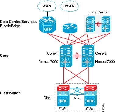
Figure 2-12 illustrates core network design options with the Cisco Nexus 7000 peering with other Cisco platforms to enable end-to-end business communication:
Figure 2-12 Cisco Nexus 7000 Campus Core Design
Campus Distribution Layer Network Design
The distribution or aggregation layer is the network demarcation boundary between wiring closet switches and the campus core network. The framework of the distribution layer system in enterprise design is based on best practices that reduce network complexities, increase reliability, and accelerate network performance. To build a strong network foundation with the three-tier model, the distribution layer plays a vital role in consolidating networks and enforcing access policies.
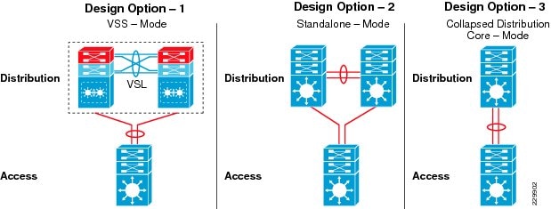
The distribution layer design options provide consistent network operation and configuration tools to enable various borderless network services. Three simplified distribution layer design options can be deployed in large, medium, and small campus locations, depending on network scale, applications used, borderless services demands, and cost, as shown in Figure 2-13. All distribution design models offer consistent network foundation services, high availability, expansion flexibility, and network scalability. However each enterprise network is different, with its own unique business challenges that require the appropriate aggregation solution. Factors that should be taken into consideration when selecting the right distribution model include scalability, high-speed network services, virtualized systems, and cost. Depending on network designs and key technical requirements, the network architect must make appropriate aggregation layer design choices to enable end-to-end borderless network services.
Figure 2-13 Distribution Layer Design Model Options
Distribution Layer Design Option 1—VSS Mode
Distribution layer design option 1 is intended for the large and medium campus network design and it is based on deploying Cisco Catalyst 6500-E Series switches using Cisco VSS, which lowers the management burden and allow multiple switches to work as one single virtualized switch, as shown in Figure 2-14.
Figure 2-14 VSS-Enabled Distribution Layer Network Design

Distribution Layer Design Option 2—Standalone Mode
Distribution layer option 2 is the traditional and proven network design used in many enterprise campus networks. It can be deployed with resilient Cisco Catalyst 6500 or 4500E switches to operate as standalone switches. This is an alternative distribution network deployment design if there is no desire to virtualize the aggregation layer switches using Cisco VSS technology. The Cisco Catalyst 6500 without Virtual Switch Link (VSL) capable supervisors can be deployed as a standalone solution, as well as the Catalyst 4500E switches.
The two single-chassis standalone mode distribution layer design options are shown in Figure 2-15.
Figure 2-15 Standalone Mode Distribution Layer Network Design
In standalone mode each Catalyst distribution switch operates independently and builds local network adjacencies and forwarding information with the access and core layers. The Layer 2 and Layer 3 protocols operate over each physical interface between the standalone distribution switches and the access layer switches. Since the core layer in the large and medium campus networks is simplified using Cisco VSS technology, the network administrator can simplify the core network topology by bundling Layer 3 interfaces into a logical EtherChannel, as shown in Figure 2-16.
Figure 2-16 Network Design with Distribution in Standalone Mode
This network design does not raise any significant concerns; each standalone distribution switch will establish Layer 3 adjacencies with core and access layer (routed access) devices to develop routing topologies and forwarding tables. The traditional multilayer network design faces the following challenges when the access layer switches communicate with two distinct distribution switches:
•The multilayer network uses simple Spanning-Tree Protocol (STP) to build Layer 2 loop-free network paths, which results in a sub-optimal and asymmetric forwarding topology.
•It requires per-VLAN virtual gateway protocol operation between aggregation switches to provide high availability. For large networks, First Hop Redundancy Protocol (FHRP) protocols may limit network scalability and consume more system and network resources.
•For a stable, secure, and optimized multilayer network, each distribution and access layer system will require advanced network parameter tuning.
•Layer 2 network recovery becomes protocol type- and timer-dependent. The default protocol parameters could result in network outages for several seconds during faults. Protocol timers can be tuned aggressively for network recovery within a second range, however it cannot meet the high-availability needs for business-class video applications like Cisco TelePresence.
Cisco innovated VSS technology to mitigate such challenges, hence it is recommended to deploy a Cisco VSS-based distribution layer infrastructure that simplifies the multilayer network and increases network capacity and performance, resulting in a highly-reliable network that provides consistent and deterministic network recovery. The traditional standalone-mode distribution layer network is an alternative solution that does not introduce any fundamental design changes.
Distribution Layer Design Option 3—Collapsed Distribution/Core Mode
The small remote campus may have several departments working on various floors within a building. Network administrators can consider collapsing the core function into the distribution layer switch for a small campus where there may only be a single distribution block. The collapsed distribution/core switch can provide network services to a small number of wiring closet switches and directly connect to the WAN edge to reach the large campus for centralized data and communication services. This solution is manageable and cost effective as long as it meets the needs of the network users and endpoints; capacity is the main factor that restricts using this model.
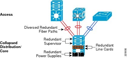
The collapsed distribution/core network can be deployed with two resilent systems as recommended in Distribution Layer Design Option 1—VSS Mode or alternatively in standalone mode as described in Distribution Layer Design Option 2—Standalone Mode. In a space-constrained small campus environment, a single Cisco Catalyst 4500E series platform can be deployed with resilient hardware to build a highly-available, collapsed distribution/core system that has the appropriate network performance, availability, and reliability required to run borderless services. With resilient hardware this solution can provide 1+1 in-chassis protection against hardware and software failure. Deploying the network in a recommended design provides consistent sub-second network recovery in the event of an unplanned outage. A single Cisco Catalyst 4500E with multiple resilient system components can be deployed as shown in Figure 2-17.
Figure 2-17 Highly Redundant Single Collapsed Distribution/Core Design
Campus Access Layer Network Design
The access layer is the first tier or entry point into the campus network; it is where end devices such as PCs, printers, cameras, phones, and so on attach to the wired and wireless campus network. The wide variety of possible types of devices that can connect and the various services and dynamic configurations that are necessary make the access layer one of the most feature-rich parts of the Borderless Campus network. Not only does the access layer switch allow users to access the network, the access layer switch provides network protection so that unauthorized users or applications do not access the network. The challenge for the network architect is determining how to implement a design that meets this wide variety of requirements, the need for various levels of mobility, and the need for a cost-effective and flexible environment, while being able to provide the appropriate balance of security and availability expected in more traditional, fixed-configuration environments. The next-generation Cisco Catalyst switching portfolio includes a wide range of fixed and modular switching platforms, each designed with unique hardware and software capabilities to function in the access layer.
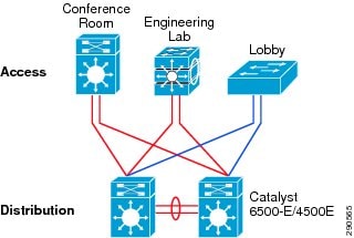
Enterprise campuses may deploy a wide range of network endpoints which all have different requirements on the network; low-latency, link speed, and low-jitter rates are just some of those requirements. The network architect must take into consideration network requirements, as well as the planned growth of the need for network resources, when determining the bandwidth requirements for the access layer to distribution uplinks. To build a high-performance distribution-access block, Cisco access layer switching platforms are designed with 10Gbps uplinks to provide borderless network services at wire-rate.
Figure 2-18 High-Performance Distribution-Access Block
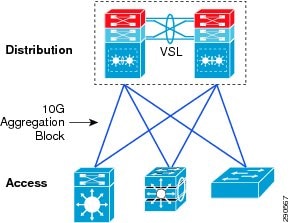
Building a 10Gbps distribution-access block provides the following benefits:
•Increased throughput—Increases network bandwidth capacity ten-fold on a per-physical-port basis. The oversubscription bandwidth ratio in high-density wiring-closet falls within the recommended range.
•High performance—Accelerates application performance by multiplexing a large number of flows onto a single high-speed connection instead of load-sharing across multiple slow aggregate links.
•Reduced TCO—The cost of access switches is less per port. Reduces additional cost to deploy fewer cables and connectors for building parallel paths between two systems.
•Simplified design—Single high-speed link to manage, operate, and troubleshoot instead of multiple individual or bundled connections.
Based on the broad-range of business communication devices and endpoints, network access demands, and capabilities, two access layer design options can be deployed, as shown in Figure 2-19.
Figure 2-19 Access Layer Design Models
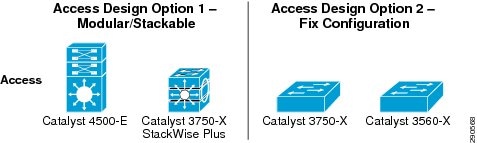
Access Layer Design Option 1—Modular/StackWise Plus Access Layer Network
Access layer design option 1 is intended to address network modularity, performance, scalability, and availability as well as the support for advanced Borderless Network services needed by the multitude of endpoints accessing the network. Implementing a modular and stackable Cisco Catalyst switching platform provides the flexibility to expand or contract the number of ports needed at the access layer, as well as allowing for modular upgrades for future requirements.
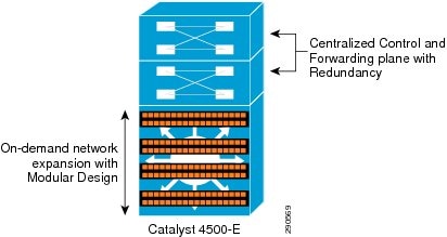
In large and medium campus deployments, the Cisco Catalyst 4500E Series platform provides a scalable, high-speed, and robust solution. In a high-density access environment, it is imperative to simplify the management of hundreds of end points through a single chassis and provide wire-speed network performance without compromising network reliability during hardware or software failures by using a non-stop forwarding architecture. The hardware architecture of the Cisco Catalyst 4500E leverages Cisco IOS software to enable borderless network services required by the access layer.
Figure 2-20 Network Edge Expansion with Modular Design
The Cisco Catalyst 3750-X Series is an alternative Cisco access layer switching platform. Using Cisco StackWise Plus technology provides flexibility and availability by clustering multiple Cisco Catalyst 3750-X Series Switches into a single high-speed stack ring that simplifies operation and allows incremental access layer network expansion or contraction. Catalyst 3750-X switches deployed in Cisco StackWise Plus mode changes network operation compared to standalone mode. When deployed in StackWise Plus mode, the switches become a single logical access layer switch, the control plane processing becomes centralized, and because of the distributed forwarding architecture, all the hardware resources gets fully utilized across all stack member switches (see Figure 2-21). Cisco StackWise Plus provides high-speed multigigabit switching capacity for network traffic switching within the stack ring and the distribution-access block can be built with multiple parallel 10Gbps uplinks for load sharing and network resiliency. The network is optimized and simplified when the cross-switch uplink ports are bundled into single logical interface using EtherChannel technology. This network design provides non-stop network communication in case of an individual stack member switch failure.
Figure 2-21 Network Edge Expansion with StackWise Plus Design

Access Layer Design Option 2—Fixed Configuration Access Layer Network
The fixed configuration switch access layer design is widely chosen for enterprise environments today as it enables quick redeployment of networking resources. The fixed configuration Cisco Catalyst switching portfolio supports a wide range of access layer technologies that allow seamless service integration and enable intelligent network management in the access layer. The fixed configuration Cisco Catalyst switches deployed as standalone switches are an ideal design choice for a small wiring closet to provide consistent borderless network services for up to 48 endpoints.
The Cisco Catalyst 3750-X and 3560-X Series switches are the recommended platforms for wired network access that can be deployed in a mixed configuration for critical and non-critical end point devices, such as Cisco IP phones, PCs, printers, and so on. For non-stop network operation during power outages, the Catalyst 3560-X requires an internal or external redundant power supply such as the Cisco RPS 2300. The increased power capacity allows flexibility when deploying enhanced Power-over-Ethernet (PoE+) on a per-port basis and with its wire-speed 10G uplink forwarding capacity, this design reduces network congestion and latency to significantly improve application performance.
To provide a consistent end-to-end user experience, the Cisco Catalyst 3750-X and 3560-X Series platforms support critical network control services to secure the access layer and intelligently provide differentiated services to various types of traffic, as well as simplified management. The Cisco Catalyst should be deployed with dual uplinks to the distribution layer for increased bandwidth capacity and network availability.
Both the modular and fixed design options offer consistent borderless network services in the access layer as well as differentiated, intelligent, and secured network access to trusted and un-trusted endpoints/devices.
Summary
The intelligent network infrastructure is at the center of the Unified Access Solution. Its proper architecture and deployment, as well as the features and configuration, are critical to the ability of the network to solve business problems. Without proper design, bottlenecks can occur, services will not be differentiated, and priorities will not be given to different types of network traffic. For too long the panacea to any network issue has been to just increase bandwidth; this is no longer the case. With network traffic increasing exponentially due to more and more services moving to the network, the network can no longer act as a dumb packet pump. It must be aware of the different traffic traversing it and it must be able to treat that traffic based on the requirements necessary to ensure that traffic reaches its destination within the requirements of the application utilizing the network. The network needs intelligence, and with the design guidance provided along with Cisco switching platforms, the network becomes the intelligence that can deliver solutions to key business problems.