Cisco Express Forwarding, CEF is advanced Layer 3 IP switching technology used on cisco router and switch. It is a feature that allows a router to quickly and efficiently make a route lookup. CEF optimizes routing table lookup by creating a special, easily searched tree structure based on the IP routing table. CEF optimizes network performance and scalability for networks with large and dynamic traffic patterns with forwarding information called the Forwarding Information Base (FIB), and the cached adjacency information called the Adjacency Table. CEF plays a crucial role in performance enhancement when it is applied in the Internet or networks with intensive web-based applications or interactive sessions. Before CEF was implemented by Cisco, routers made routing decisions based on 2 methods i.e. packet-switching-Process- Switching and Fast-Switching.
Routers make decisions about forwarding packets based on the source and the destination addresses. This decision-making process is called “switching.” Let us not get confused with an Ethernet switch. The Switching referred above is what a router does when it makes the following decisions:
- Whether or not to forward the packet after checking that the destination mentioned in the packet is reachable or not
- If the destination is reachable, what is the next-hop?, and what interface the router will use to get to that destination?
- Whether or not to modify the Ethernet MAC on the packet?
ROUTER ARCHITECTURE divides router functions into three operational planes:
MANAGEMENT PLANE: This plane is used to manage a device through its connection to the network. Examples of protocols processed in the management plane include Simple Network Management Protocol (SNMP), Telnet, File Transfer Protocol (FTP), Secure FTP, and Secure Shell (SSH). These management protocols are used for monitoring and command-line interface (CLI) access.
CONTROL PLANE: The control plane is the brain of the router. Its main function is to maintain sessions and exchange protocol information with other routers or network devices. Following are some of the functions of the control plane:
- Decides where traffic is going (i.e. routing protocols, etc.)
- System configuration, management information
- Exchange topological information
- Policing (Management Plane Protection)
DATA PLANE: Its main function is to forward data through a router (ASIC). For example, end-user traffic traveling from a user’s PC to a web server on a different network would go across the data plane. (It means the data packets will be processed by the hardware itself for the routing decisions before they are forwarded towards their destination based on the routing decisions). Following are some of the functions of the Data Plane:
- Forwarding data packets hence often called the Forwarding Plane
- Utilize the control plane to forward onto the destination
- Utilize the control plane to make packet drop decisions
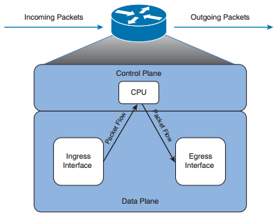
Data plane and control plane together are responsible for the speed at which the packets can flow through a router. We will consider these two planes of operation and examine three different approaches that Cisco routers can take. This applies to all the packets arriving on an ingress interface and being sent out an appropriate egress interface.
Cisco routers support the following three primary modes of packet switching:
- 1. Process switching
- 2. Fast switching
- 3. Cisco Express Forwarding (CEF)
- 1. PROCESS-SWITCHING – When the data packets enter an interface, the Route Processor (the CPU) must be involved in every packet forwarding decision
- It works with every packet for L2 address alternation and other error checking like CRC etc.
- Get the next hop L2 address via the ARP table.
- Route table lookup for every packet.
- slower speed and more CPU intensive
NOTE: An interface can be configured for process switching by disabling fast switching on that interface. The command used to disable fast switching is:RTR-2(config)#no ip route-cache
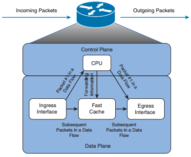
- 2. FAST-SWITCHING – When a data flow enters an interface, if the destination is not stored in the “Route Cache” for that interface, it is “Punted” to the “Route Processor” (CPU) to check the IP Route table for a destination.
- It is similar to “process-switching” but maintains a route-cache
- For Source and destination base traffic use route-cache
- Less CPU intensive, faster than previous technology
- Fast-switching is based on software hence it has a cache updating problem.
NOTE: Fast switching can be configured on an interface configuration mode with the command RTR-2(config)#ip route-cache
- 3. CISCO EXPRESS FORWARDING (CEF)
- It’s similar to fast-switching but CEF uses hardware base ASIC for forwarding.
- For forwarding, CEF uses both FIB and Adjacency Table.
- It’s very less CPU intensive and provides faster speed/wire-speed
- Updates it’s FIB/Adjacency immediately
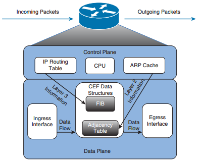
THE CEF PROCESS FLOW:
- When a packet enters the router, the router strips off the Layer 2 information.
- The router looks up the destination IP address in the CEF table (FIB), and it makes a forwarding decision.
- The result of this forwarding decision points to one adjacency entry in the adjacency table.
- The information retrieved from the adjacency table is the Layer 2 rewrite string, which enables the router to put a new Layer 2 header onto the frame,
- The packet is switched out onto the outgoing interface toward the next hop.
NOTE:- On many platforms, CEF is enabled by default. If it is not, you can globally enable it with the following command RTR-2(config)#ip cef
If CEF is enabled globally but is not enabled on a specific interface, you can enable it on that interface with the interface configuration command
RTR-2(config-if)#interface gigabitEthernet 0/2
RTR-2(config-if)#ip route-cache cef
CEF COMPONENTS
Cisco Express Forwarding is made up of two main components: the Forwarding Information Base (FIB) and the Adjacency Table. These are automatically updated at the same time as the routing table.
Forwarding Information Base (FIB)
The FIB contains destination reachability information i.e. CEF table/FIB table which holds the essential information, taken from the routing table, to be able to make a forwarding decision for a received IP packet. This information includes the IP prefix, the recursively evaluated next hop, and the outgoing interface.
Adjacency Table
It is responsible for the MAC or Layer 2 rewrite. This adjacency can be built from ATM, Frame Relay map statements, dynamic information learned from Ethernet-ARP, inverse ARP on ATM, or Frame Relay. The Layer 2 rewrite string contains the new Layer 2 header which is used on the forwarded frame. For Ethernet, this is the new destination and source MAC address and the Ethertype. For PPP, the Layer 2 header is
The adjacency table contains many different types of adjacency:
- Host route adjacency: A host route adjacency entry is used to specify that a specific host is within one or layer two hops.
- Null adjacency: This is used for packets that are destined for the Null0 interface. It can be used as a form of access filtering.
- Glean adjacency: A glean adjacency is used when a device is connected to multiple hosts of the same interface. In this case, the entry contains a prefix for the subnet not just for a specific host entry.
- Punt adjacency: This is used for those packets that utilize features not currently supported by CEF and which must be forwarded (punted) to the next switching level (often to be process switched).
- Discard adjacency: A discard adjacency entry is used for those packets that are to be automatically dropped.
- Drop adjacency: A drop adjacency entry is used for those packets which dropped but only after the prefix is checked.
CEF LOAD BALANCING
CEF supports two modes of load sharing:
PER-PACKET: Per Packet load balancing method creates traffic distribution on a round-robin fashion i.e. to say that a router sends one packet for destination over the first path, the second packet for the same destination over the second path, third again at the first path and so on. Per packet load balancing is useful when equal utilization of paths to the same destination is required. This method avoids path congestion too.
PER-DESTINATION (PER-FLOW): Per Destination Load balancing is the default load-balancing method enabled on the router. Packets for a given source-destination host pair will take the same path, even if multiple paths are available. In case the majority of traffic is for the same source and destination pair, traffic will use the same path leading to underutilization of other paths. Per Destination is the preferred load balancing for most situations.
We can change the load-sharing method on a per-interface basis, but the availability of this command might be limited depending on the hardware capabilities of the device. (Often hardware-based multilayer switches don’t have this capability while software-based ISR routers do).
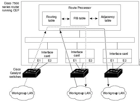
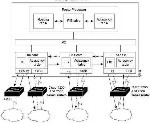
CENTRAL Vs DISTRIBUTED CEF
CENTRAL CEF MODE – When CEF mode is enabled, the CEF FIB and adjacency tables reside on the route processor, and the route processor performs the express forwarding. You can use CEF mode when line cards are not available for CEF switching, or when you need to use features not compatible with distributed CEF switching.
DISTRIBUTED CEF – (dCEF) mode – When dCEF is enabled, line cards maintain identical copies of the FIB and adjacency tables. The line cards can perform the express forwarding by themselves, relieving the main processor – Gigabit Route Processor (GRP) – of involvement in the switching operation.
CEF LAB
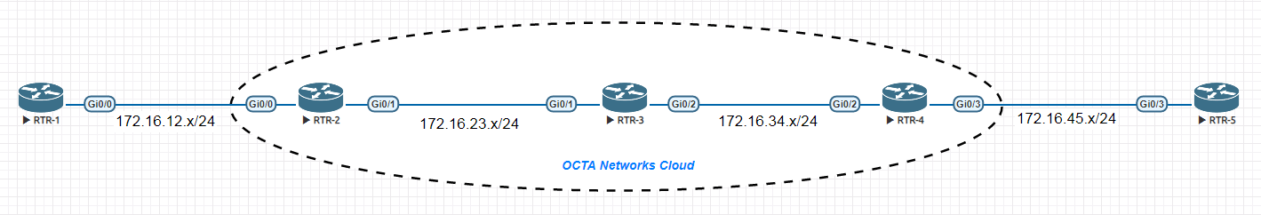
Let us have a look at the example configuration and verification of the CEF operation. In the topology given below, we are running OSPF area0 on RTR-2, RTR-3, and RTR-4, we are not considering RTR-1 and RTR-5 devices in this discussion.
IPv4/IPv6 CEF configuration
| Central CEF | Distributed CEF |
|---|---|
| RTR-2(config)#ip cef | RTR-2(config)#ip cef distributed |
| RTR-2(config)#ipv6 cef | RTR-2(config)#ipv6 cef distributed |
| For IPv6 Cef IPv6 unicast-routing must be enabled | For IPv6 Cef IPv6 unicast-routing must be enabled |
| RTR-2(config)#no ip cef | RTR-2(config)#no ip cef distributed |
| You can disable IP cef with the above command | %Cannot disable CEF on this platform You cannot disable IP CEF on a Distributed platform |
The given output tells us that we have full reachability between OCTA networks cloud. Let us look closer for the CEF output.
RTR-2#ping 192.1.3.3 source loo 0

Type escape sequence to abort.
Sending 5, 100-byte ICMP Echos to 192.1.3.3, timeout is 2 seconds:
Packet sent with a source address of 192.1.2.2
!!!!!
Success rate is 100 percent (5/5), round-trip min/avg/max = 3/3/3 ms

RTR-2#ping 192.1.4.4 source loo 0
Type escape sequence to abort.
Sending 5, 100-byte ICMP Echos to 192.1.4.4, timeout is 2 seconds:
Packet sent with a source address of 192.1.2.2
!!!!!
Success rate is 100 percent (5/5), round-trip min/avg/max = 4/5/8 ms
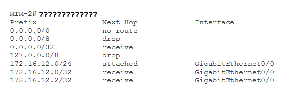
You can view the CEF table by issuing the command sh ip cef
Prefix               Next Hop             Interface
0.0.0.0/0            no route
0.0.0.0/8            drop
0.0.0.0/32           receive
127.0.0.0/8          drop
172.16.12.0/24       attached             GigabitEthernet0/0
172.16.12.0/32       receive              GigabitEthernet0/0
172.16.12.2/32       receive              GigabitEthernet0/0
172.16.12.255/32     receive              GigabitEthernet0/0
172.16.23.0/24       attached             GigabitEthernet0/1
172.16.23.0/32       receive              GigabitEthernet0/1
172.16.23.2/32       receive              GigabitEthernet0/1
172.16.23.3/32       attached             GigabitEthernet0/1
172.16.23.255/32     receive              GigabitEthernet0/1
172.16.34.0/24       172.16.23.3          GigabitEthernet0/1
172.16.45.0/24       172.16.23.3          GigabitEthernet0/1
192.1.2.2/32         receive              Loopback0
192.1.3.3/32         172.16.23.3          GigabitEthernet0/1
192.1.4.4/32         172.16.23.3          GigabitEthernet0/1
224.0.0.0/4          drop
224.0.0.0/24         receive
240.0.0.0/4          drop
Prefix               Next Hop             Interface
255.255.255.255/32   receive
RTR-2#
attached: represents a network to which the router is directly attached
receive: represents an IP address on one of the router’s interfaces
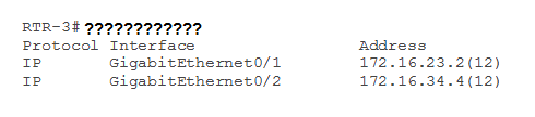
let us check the adjacency table on RTR-3 as it is connected to RTR-2 and RTR-4
RTR-3#show adjacency
Protocol Interface                 Address
IP       GigabitEthernet0/1        172.16.23.2(12)
IP       GigabitEthernet0/2        172.16.34.4(12)
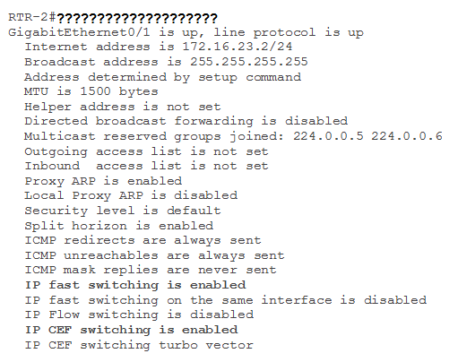
Interface level information about cef on RTR-2
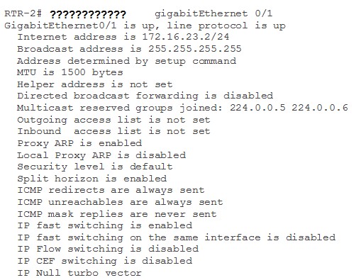
  RTR-2#show ip interface gigabitEthernet 0/1
  GigabitEthernet0/1 is up, line protocol is up
  Internet address is 172.16.23.2/24
  Broadcast address is 255.255.255.255
  Address determined by setup command
  MTU is 1500 bytes
  Helper address is not set
  Directed broadcast forwarding is disabled
  Multicast reserved groups joined: 224.0.0.5 224.0.0.6
  Outgoing access list is not set
  Inbound  access list is not set
  Proxy ARP is enabled
  Local Proxy ARP is disabled
  Security level is default
  Split horizon is enabled
  ICMP redirects are always sent
  ICMP unreachables are always sent
  ICMP mask replies are never sent
  IP fast switching is enabled
  IP fast switching on the same interface is disabled
  IP Flow switching is disabled
  IP CEF switching is enabled
  IP CEF switching turbo vector
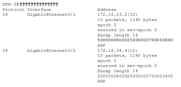
To see the Layer 2 header information we need to user details keyword to end of the show adjacency
RTR-3#show adjacency  detail
Protocol Interface                 Address
IP       GigabitEthernet0/1        172.16.23.2(12)
                                   10 packets, 1140 bytes
                                   epoch 0
                                   sourced in sev-epoch 0
                                   Encap length 14
                                   5000000600015000000700010800
                                   ARP
IP       GigabitEthernet0/2        172.16.34.4(12)
                                   10 packets, 1140 bytes
                                   epoch 0
                                   sourced in sev-epoch 0
                                   Encap length 14
                                   5000000800025000000700020800
                                   ARP
We can see there’s an entry for 172.16.23.2
5000000600015000000700010800
What does this number mean? It’s the MAC addresses of the source and destination that we require and the Ethertype…let me break it down for you:
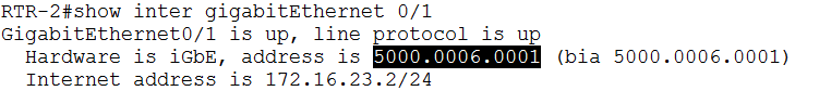
500000060001 is MAC address of RTR-2 interface giga 0/1
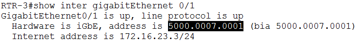
500000070001is MAC address of RTR-3 interface giga 0/1
0800 is the Ethertype. 0x800 stands for IPv4.
Let us check on RTR-3 what ARP entries are created for RTR-2 and RTR-4.
RTR-3#show ip arp  172.16.23.2
Protocol  Address          Age (min)  Hardware Addr   Type   Interface
Internet  172.16.23.2           134   5000.0006.0001  ARPA   GigabitEthernet0/1

RTR-3#show ip arp  172.16.34.4
Protocol  Address          Age (min)  Hardware Addr   Type   Interface
Internet  172.16.34.4           136   5000.0008.0002  ARPA   GigabitEthernet0/2
We can see that the values under the “Hardware Addr” field match the first twelve digits in the Layer 2 header information in the previous show command.
To verify the status of load balancing on RTR-2 with show ip cef exact-‐route command
RTR-2#show ip cef exact-route 192.1.2.2 192.1.4.4
192.1.2.2 -> 192.1.4.4 =>IP adj out of GigabitEthernet0/1, addr 172.16.23.3
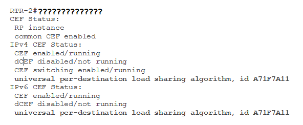
Let us check default load sharing behaviors on RTR-2
  RTR-2#show cef state
CEF Status:
 RP instance
 common CEF enabled
IPv4 CEF Status:
 CEF enabled/running
 dCEF disabled/not running
 CEF switching enabled/running
 universal per-destination load-sharing algorithm, id A71F7A11

IPv6 CEF Status:
 CEF enabled/running
 dCEF disabled/not running
 universal per-destination load sharing algorithm, id A71F7A11
CHALLENGE TROUBLESHOOTING
1-1. Based on the exhibit provided what show command was executed on RTR-2?
1-2. Based on the exhibit provided what show command was executed on RTR-2?
1-3. Based on the exhibit provided what show command was executed on RTR-3?
1-4. Based on the exhibit provided what show command was executed on RTR-2?

1-5. Based on the exhibit provided what show command was executed on RTR-3?
1-6. Based on the exhibit provided what show command was executed on RTR-2?
1-7. what is wrong with this exhibit?